



You open a shortlist of "electrical engineering software" and half the tools solve completely different problems. One simulates transistor behavior at the nanosecond level. Another routes copper traces on a six-layer board. A third models a substation feeding 40,000 homes. Calling all of these the same category is where most buying decisions go wrong.
Electrical engineering is not one job, so the software is not one category. Circuit simulation, PCB layout, power systems analysis, numerical computing, and multiphysics each solve a distinct problem, and the "best" tool depends entirely on which problem you are trying to validate first. The market reflects this breadth. The global electrical engineering software market is projected to grow from $5.98 billion in 2025 to $13.22 billion by 2034, at a 9.2% CAGR, according to Dataintelo (2025). The broader engineering software market is forecast to climb from $53.92 billion in 2025 to $246.51 billion by 2034 at an 18.45% CAGR, per Precedence Research (2025).
That growth is fueling more specialized tools, not fewer, which makes matching software to workflow harder, not easier. If you evaluate tools the way many teams evaluate any technical product, through hands-on validation rather than feature checklists, you already know the trap: a demo that looks impressive can hide a workflow mismatch. The same logic applies here. Before you commit budget or a semester of learning time, it helps to see the category the way engineers actually use it. If you also work adjacent to design tooling decisions, our roundup of ai design tools covers a neighboring space, and teams standardizing documentation across engineering functions often review component content management systems too.
What's inside
This guide is a use-case-first shortlist of essential electrical engineering software for students, early-career engineers, designers, and technical evaluators who need to match a tool to a specific workflow. It covers circuit design software, PCB and EDA tools, power systems software, numerical computing, and multiphysics simulation.
We selected these nine tools based on four criteria: use-case coverage across major electrical subdomains, real adoption among practicing engineers, breadth of workflows each tool supports, and clarity of the job each one does best. The goal is not to crown one winner. It is to help you decide what to validate first, then pick the tool that fits.
TL;DR
- Best for numerical computing and model development: MATLAB, the go-to for algorithm development, control systems, and signal processing.
- Best free circuit simulation: LTspice, a fast SPICE simulator for analog and power designs at no cost.
- Best PCB design workflow: Altium Designer, an integrated ECAD platform from schematic to production.
- Best power systems analysis: ETAP, an electrical digital twin for load flow, protection, and short circuit studies.
- Best electromagnetic transient studies: PSCAD, purpose-built for utility and grid transient analysis.
- Best multiphysics simulation: ANSYS, for when electrical design intersects with heat, mechanics, and system validation.
No single tool covers every workflow. The best electrical software is the one that matches the problem in front of you.
What is electrical engineering software?
Electrical engineering software is a family of design, simulation, and analysis tools that engineers use to model, verify, and document electrical systems before building them in hardware. The category spans several distinct software families, each aimed at a different level of the design stack.
The major families you will encounter:
- Circuit simulation: Models how analog, digital, and mixed-signal circuits behave before you build a board. SPICE-based tools dominate here.
- PCB and EDA: Handles schematic capture, board layout, routing, and manufacturing documentation. These electronic design automation (EDA) tools turn a design into a manufacturable board.
- Power systems: Analyzes system-level electrical behavior such as load flow, short circuit, protection coordination, and arc flash across grids and industrial plants.
- Numerical computing: Provides a programming environment for algorithm development, control system design, signal processing, and engineering math.
- Multiphysics and thermal analysis: Simulates how electrical designs interact with heat, mechanical stress, and electromagnetic fields.
What software for electrical engineers typically enables:
- Validate designs before committing to hardware or a physical build.
- Catch failures, tolerance issues, and instability early, when they are cheap to fix.
- Turn schematics into manufacturable, documented deliverables.
- Model system behavior under fault, load, and transient conditions.
- Automate calculation, analysis, and reporting workflows.
The practical takeaway: what software do electrical engineers use depends on the layer they work at. A student verifying an op-amp circuit needs something different from a utility engineer studying grid transients. That distinction drives the rest of this guide.
When to use each type of tool
Choosing electrical engineering design software starts with the job, not the brand. Here is how to match the three most commonly confused categories to real work.
Choose circuit simulation before prototyping
Engineers simulate circuits before building hardware because prototype spins are slow and expensive. Circuit simulation before prototyping lets you validate a design, sweep component tolerances, and catch instability or thermal issues on screen instead of on a bench. A SPICE run that takes minutes can save weeks of board revisions. Use this class of tool when you are verifying analog behavior, mixed-signal timing, or power supply response.
Choose PCB and EDA tools when the design needs to become manufacturable
Once a circuit is validated, it has to become a physical board. PCB design software handles schematic capture, component placement, routing, and the documentation a fabricator needs. This is where a concept becomes a manufacturable deliverable with a bill of materials, layer stackup, and fabrication files. Reach for EDA tools when your team is moving from proven concept to board production.
Choose power systems software when working on grid, protection, or distribution problems
Power systems software solves a different class of problem entirely. These platforms model system-level behavior, not individual components. Power system analysis covers load flow, short circuit calculations, protection coordination, and arc flash studies across distribution networks, industrial plants, and utility grids. Use these tools when your questions are about how an entire electrical system behaves under load and fault, not how a single circuit performs.
Comparison table
Here is a use-case-first view of all nine tools. Pricing and ratings shift over time, so treat these as directional and confirm current figures on each vendor's site.
| # | Product | Intent | Key use case | Pricing | G2 rating |
|---|---|---|---|---|---|
| 1 | MATLAB | Numerical computing | Algorithm development, control systems, signal processing | From USD 1,050/yr | 4.5/5 |
| 2 | LTspice | Circuit simulation | Free analog and power circuit simulation | Free | Not listed |
| 3 | Altium Designer | PCB and EDA | Schematic capture to board production | From USD 355/mo | 4.6/5 |
| 4 | ETAP | Power systems | Load flow, protection, short circuit studies | Quote-based | 4.3/5 |
| 5 | PSpice | Circuit simulation | Analog and mixed-signal verification | From USD 1,280/yr | 4.4/5 |
| 6 | OrCAD | PCB and EDA | Schematic capture, layout, simulation | Quote-based | 4.2/5 |
| 7 | PSCAD | Power systems | Electromagnetic transient simulation | Free Edition available | 4.5/5 |
| 8 | Solid Edge | CAD / electromechanical | Mechanical design, assemblies, sheet metal | Free tiers available | Not listed |
| 9 | ANSYS | Multiphysics simulation | Thermal, electromagnetic, structural analysis | Quote-based | 4.4/5 |
The 9 best electrical engineering software tools
1. MATLAB
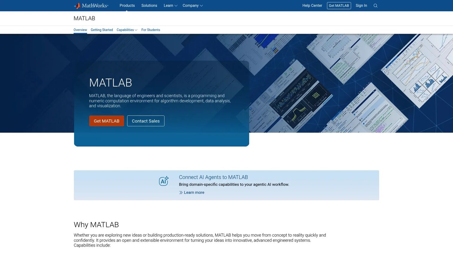
MATLAB is a technical computing environment for numerical analysis, visualization, and algorithm development. It shows up on nearly every broad electrical engineering list because it sits above any single subdomain: engineers use it to model control systems, process signals, develop algorithms, and run simulation work that feeds into hardware and firmware decisions. MATLAB for electrical engineering is less about one task and more about the math and modeling layer that connects them.
Best for: Engineers, scientists, and researchers doing numerical computing and simulation across control, signal, and system design.
Key strengths
- Data analysis and visualization: Turn raw measurement data into plots, transforms, and models without leaving the environment.
- Programming and app building: Write, test, and package algorithms, then build interactive apps around them.
- Broad integration: Connect to Python, C/C++, Fortran, and Java to fit existing engineering toolchains.
Why choose MATLAB: MATLAB fits engineers who live in the modeling and analysis layer rather than in schematic or board work. It is the tool for control system design, signal processing pipelines, and algorithm prototyping that later informs hardware. If your work is math-heavy and simulation-first, this is the anchor of the stack.
MATLAB pricing: MathWorks lists an individual annual MATLAB license at USD 1,050.00. A MATLAB and Simulink Home Suite annual option is listed at USD 165.00 for non-commercial use. Perpetual and use-case-specific licensing options are also available. There is no free tier, though MathWorks offers trial access.
2. LTspice
LTspice is a free SPICE simulator with schematic capture and a built-in waveform viewer, maintained by Analog Devices. It is the default answer for engineers who want circuit simulation before prototyping without a license cost. LTspice handles analog and power designs quickly, which is why it lives on so many benches, from student labs to production power supply design.
Best for: Engineers needing free, fast circuit simulation for analog and power designs.
Key strengths
- Fast, free SPICE simulation: Run analog and mixed-signal circuit simulation with no license fee and no run limits.
- Schematic capture and waveform viewer: Build a circuit and inspect the results in one connected workflow.
- Model and demo library: Start from a large macromodel and example circuit library instead of a blank page.
Why choose LTspice: LTspice is the practical choice when you need to verify analog behavior, sweep component values, or validate a power supply design fast. It removes the cost barrier entirely, so students and professionals reach for it as a first-pass simulation software before committing to a board.
LTspice pricing: LTspice is free. Analog Devices provides unlimited downloads with no public paid tiers, along with tutorials, technical guides, and a demo circuit library.
3. Altium Designer

Altium Designer is PCB design software that unifies schematic capture, board layout, routing, simulation, and collaboration in one platform. It is the reference point for professional board work because it keeps the entire path from schematic to production inside a single integrated ECAD environment. For engineering teams moving a validated circuit toward a manufacturable board, that unified workflow is the draw.
Best for: Professional PCB designers and engineering teams needing an integrated ECAD platform.
Key strengths
- Schematic capture and advanced routing: Design the circuit and lay out complex, high-density boards in one place.
- SPICE simulation and 3D-MID design: Validate circuits and model board geometry without leaving the tool.
- Supply chain and BOM management: Track components, variants, and real-time bill of materials data against supply availability.
Why choose Altium Designer: Altium fits teams that want schematic, layout, simulation, and documentation to live in one integrated environment rather than stitched across tools. It suits professional hardware teams shipping real products, with variant management, harness design, and supply chain intelligence built in. The tradeoff is that its depth rewards teams committed to it as a primary platform.
Altium Designer pricing: Altium lists three public plans. Standard starts at USD 355/month, Pro at USD 460/month, and Enterprise is contact-sales custom pricing. There is no free tier.
4. ETAP

ETAP is an electrical digital twin and power systems software platform for designing, simulating, operating, and optimizing electrical power systems. It serves system engineers, not circuit designers. Where a SPICE tool models a single circuit, ETAP models entire networks, which makes it the platform of choice for utility, infrastructure, and industrial power work.
Best for: Utilities, infrastructure, and industrial teams doing electrical power system engineering and operations.
Key strengths
- Power system analysis and simulation: Run load flow, short circuit, and protection coordination studies across a full network.
- Electrical digital twin modeling: Build one-line diagrams that mirror the real system for design and planning.
- Real-time monitoring and operations: Connect to SCADA and live operations for monitoring beyond design-stage analysis.
Why choose ETAP: ETAP fits engineers whose questions are system-level: how a network behaves under fault, how protection devices coordinate, and how to plan capacity. It is built for power system analysis at the grid and plant scale, not for verifying a component-level circuit. That system-first scope is exactly why power engineers standardize on it.
ETAP pricing: ETAP uses quote-based pricing through a self-service request form, so public figures are not listed. The site offers a free 30-day software demo for evaluation.
5. PSpice
PSpice is Cadence's circuit simulation software for analog, mixed-signal, and advanced analysis workflows. Like LTspice, it is a SPICE-based tool for circuit simulation before prototyping, but it sits inside a broader Cadence design ecosystem with a large model library and deeper analysis engines. Engineers use it to verify analog and mixed-signal designs where advanced analysis and model breadth matter.
Best for: Engineers needing circuit simulation and verification for analog and mixed-signal designs.
Key strengths
- Virtual SPICE environment: Simulate with a large built-in model library covering many real components.
- Analog, mixed-signal, and advanced engines: Run beyond basic transient and DC analysis into advanced verification.
- MATLAB and Simulink co-simulation: Link circuit simulation with system-level modeling for combined workflows.
Why choose PSpice: PSpice fits engineers who want circuit simulation tied into a larger EDA and design-analysis ecosystem rather than a standalone simulator. Its advanced analysis engines and co-simulation with MATLAB and Simulink suit teams doing more than first-pass verification. It is a strong fit when your simulation work connects to broader board and system design.
PSpice pricing: Cadence surfaces PSpice through OrCAD X subscription tiers rather than a standalone price. OrCAD X Standard is listed at USD 1,280.00/year, and OrCAD X Professional Plus is contact-for-pricing. Cadence offers a free trial.
6. OrCAD

OrCAD is a PCB design and simulation suite covering schematic capture, board layout, analysis, and cloud collaboration. It sits alongside PSpice in the Cadence family, giving design teams an EDA stack where schematic, layout, and simulation connect. For teams managing board development end to end, OrCAD offers the design automation workflow in one lineage of tools.
Best for: PCB design teams needing schematic capture, PCB layout, and simulation in one suite.
Key strengths
- Schematic capture and PCB layout: Move from schematic to routed board within a single connected suite.
- PSpice simulation across tiers: Bring circuit simulation into the same environment as your board design.
- OrCAD X OnCloud collaboration: Manage design data and collaborate through cloud-based tooling.
Why choose OrCAD: OrCAD fits teams that want EDA tools with an established simulation lineage and cloud collaboration built in. Because it shares the Cadence ecosystem with PSpice, circuit simulation and PCB design software workflows stay connected. It suits design teams that value that integration across the board development lifecycle.
OrCAD pricing: Cadence lists three OrCAD X tiers, Standard, Professional, and Professional Plus. Pricing varies by region and is surfaced through a Cadence Channel Partner rather than a public price. A free trial is available.
7. PSCAD
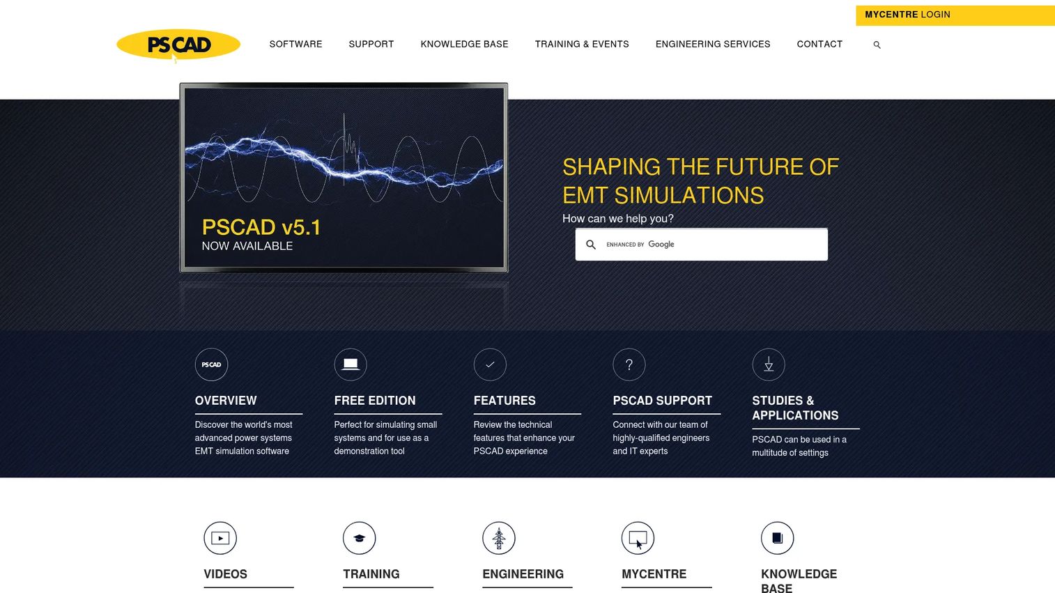
PSCAD is power system electromagnetic transient simulation software, providing a graphical interface to the EMTDC engine. It is purpose-built for the transient side of power systems software, where engineers study fast electromagnetic events across grids, protection schemes, and equipment. Utility, OEM, and research teams reach for it when steady-state analysis is not enough and they need to model transients.
Best for: Utility, OEM, and research teams doing electromagnetic transient and power system studies.
Key strengths
- Graphical power system modeling: Build and simulate networks visually on top of the EMTDC engine.
- Simulation sets and multiple runs: Configure and run many EMTDC scenarios for comprehensive studies.
- 64-bit application support: Handle larger, more detailed models without legacy constraints.
Why choose PSCAD: PSCAD fits engineers whose power work centers on electromagnetic transients, such as fault studies, switching events, and protection analysis. It complements steady-state power system analysis tools by handling the fast, dynamic phenomena they are not built for. That transient focus makes it a staple in utility and grid research.
PSCAD pricing: PSCAD offers a publicly listed Free Edition. Paid and licensed editions with maintenance are available, but public numeric pricing is not shown on the site.
8. Solid Edge
Solid Edge is Siemens' 2D and 3D CAD and product development suite. It is not electrical-specific, but it earns a place on this list because electrical work rarely happens in isolation. Engineers on interdisciplinary teams use it for mechanical design, enclosure and assembly work, and collaboration with the electromechanical side of a product. When your electrical design has to fit inside a real physical product, CAD becomes part of the workflow.
Best for: Teams needing professional CAD for mechanical design, assemblies, and sheet metal work.
Key strengths
- Synchronous technology: Combine direct and parametric modeling in one design approach.
- Sheet metal design tools: Design enclosures and metal parts that house electrical assemblies.
- Assembly modeling and management: Manage large assemblies where electrical and mechanical parts meet.
Why choose Solid Edge: Solid Edge fits electrical engineers who work across disciplines, especially where enclosures, mounting, and mechanical fit matter. It is not a circuit or PCB tool, so treat it as the mechanical companion to your electrical stack rather than a replacement for EDA tools. For product teams, that electromechanical collaboration is the value.
Solid Edge pricing: Siemens offers a free Community Edition and a free annual subscription for qualifying startups. Monthly and annual paid subscriptions are available through the Siemens site, though public numeric pricing was not listed at the time of writing.
9. ANSYS

ANSYS is an engineering simulation company providing physics-based tools for design, analysis, and multiphysics workflows. It matters for electrical engineering when a design stops being purely electrical and starts intersecting with heat, mechanical stress, or electromagnetic fields. Multiphysics simulation is where high-complexity teams validate how a design behaves across coupled physical domains, not just on a schematic.
Best for: Enterprises and engineering teams needing advanced, physics-based simulation.
Key strengths
- Physics-based simulation and analysis: Model electromagnetic, thermal, and structural behavior on a shared foundation.
- Multiphysics workflows: Simulate coupled effects, such as how current heats a component and stresses its housing.
- Cloud-connected HPC options: Run large simulations with cloud and high-performance computing support.
Why choose ANSYS: ANSYS fits teams whose electrical work depends on how designs behave thermally, mechanically, and electromagnetically together. It is the tool for multiphysics simulation and system-level validation at the higher end of engineering complexity. Reach for it when component-level circuit simulation and board design are done, and the question becomes how the whole thing survives real physical conditions.
ANSYS pricing: ANSYS pricing is product- and quote-dependent, so no public general price is listed. Free trial access is available for selected products.
Considerations before you choose
A shortlist is only useful if you filter it against your actual work. Run any candidate through these criteria before committing budget or learning time.
Workflow fit
Match the tool to the layer you work at, not the category label. Circuit simulation, PCB design, power systems, and multiphysics solve different problems. The first question is always which problem you need to validate first, then pick the tool built for that layer.
Learning curve and ramp time
Some tools reward a weekend of exploration; others expect months of investment. Weigh how deep you will go against how fast you need output. A free simulator you can learn in an afternoon may beat a heavyweight platform for a one-off validation.
Integration with your existing stack
Check how the tool exchanges data with what you already use. MATLAB co-simulation, PSpice-to-OrCAD lineage, and CAD-to-ECAD handoffs all matter when your work crosses tools. Isolated tools create manual rework at every boundary.
Cost and licensing model
Pricing ranges from free (LTspice, PSCAD Free Edition) to quote-based enterprise platforms. Match the licensing model to your context: a student, a small team, and a utility have very different needs. Confirm current pricing directly with each vendor, since figures change.
Team size and collaboration
A solo project has different needs than a distributed engineering team. Look at version control, shared libraries, and collaboration features when more than one person touches the design. Tools built for teams pay off as headcount grows.
Conclusion
There is no single best electrical engineering software, and any list that crowns one winner is answering the wrong question. The right tool depends entirely on the workflow in front of you.
For numerical computing and model development, MATLAB anchors the stack. For free circuit simulation before prototyping, LTspice is hard to beat, with PSpice serving deeper analysis needs. For PCB design software and manufacturable boards, Altium Designer and OrCAD lead. For power systems software, ETAP handles system-level studies and PSCAD covers electromagnetic transients. For multiphysics simulation, ANSYS is the tool when electrical design meets heat and mechanics. Solid Edge fills the electromechanical CAD gap for interdisciplinary teams.
The practical move is simple: identify the problem you need to validate first, then start with the tool built for that layer. Most engineers end up running two or three of these electrical software tools together, matched to the different jobs their work demands. Start narrow, prove value, then expand your stack as the work requires it.
FAQs
It depends on the job, not a single favorite. Engineers doing numerical computing and controls lean on MATLAB, those verifying circuits use LTspice or PSpice, board designers use Altium Designer or OrCAD, and power engineers use ETAP or PSCAD. ANSYS covers multiphysics work when electrical design intersects with heat and mechanics. Most engineers use two or three of these together.
The best choice depends on what the student needs to learn. For circuit simulation, LTspice is free and beginner-friendly. For numerical computing and coursework math, MATLAB is standard and often available through student licenses. For PCB design, a student edition of an EDA tool is a good entry point. Start with the category that matches your current course or project.
SPICE-based tools like LTspice and PSpice are the standard for circuit simulation before prototyping. They let you validate analog and mixed-signal behavior, sweep component values, and catch instability on screen. This reduces costly board revisions, since a fix in simulation is far cheaper than a re-spin in hardware.
Altium Designer and OrCAD are two of the most common PCB design software choices. Both handle schematic capture, component placement, routing, and the documentation a fabricator needs to build the board. The right pick depends on whether you want a single integrated ECAD platform or an EDA stack tied to a broader simulation lineage.
ETAP and PSCAD are common in system-level electrical work. ETAP handles load flow, short circuit, and protection coordination studies across networks, while PSCAD focuses on electromagnetic transient simulation. Both differ from component-level circuit simulation because they model how an entire electrical system behaves under load and fault, not how a single circuit performs.
Yes, widely. MATLAB for electrical engineering fits the modeling and analysis layer: control system design, signal processing, algorithm development, and simulation work. It is not a replacement for circuit or PCB tools, but rather the numerical computing environment that feeds into hardware and firmware decisions across many subdomains.
No. Circuit simulation, PCB design, power systems, and multiphysics are genuinely different problems that need purpose-built tools. A SPICE simulator will not route a board, and a PCB tool will not model grid transients. The practical approach is to use the tool matched to each workflow rather than forcing one package to do everything.
Start with the workflow you need to validate first, then weigh team size, learning curve, integration with your existing stack, and licensing cost. A free simulator may be perfect for a one-off validation, while a distributed team building products needs collaboration features and an integrated platform. Match the tool to the problem, not to brand reputation.